Sunday, January 11, 2015

Final Rack

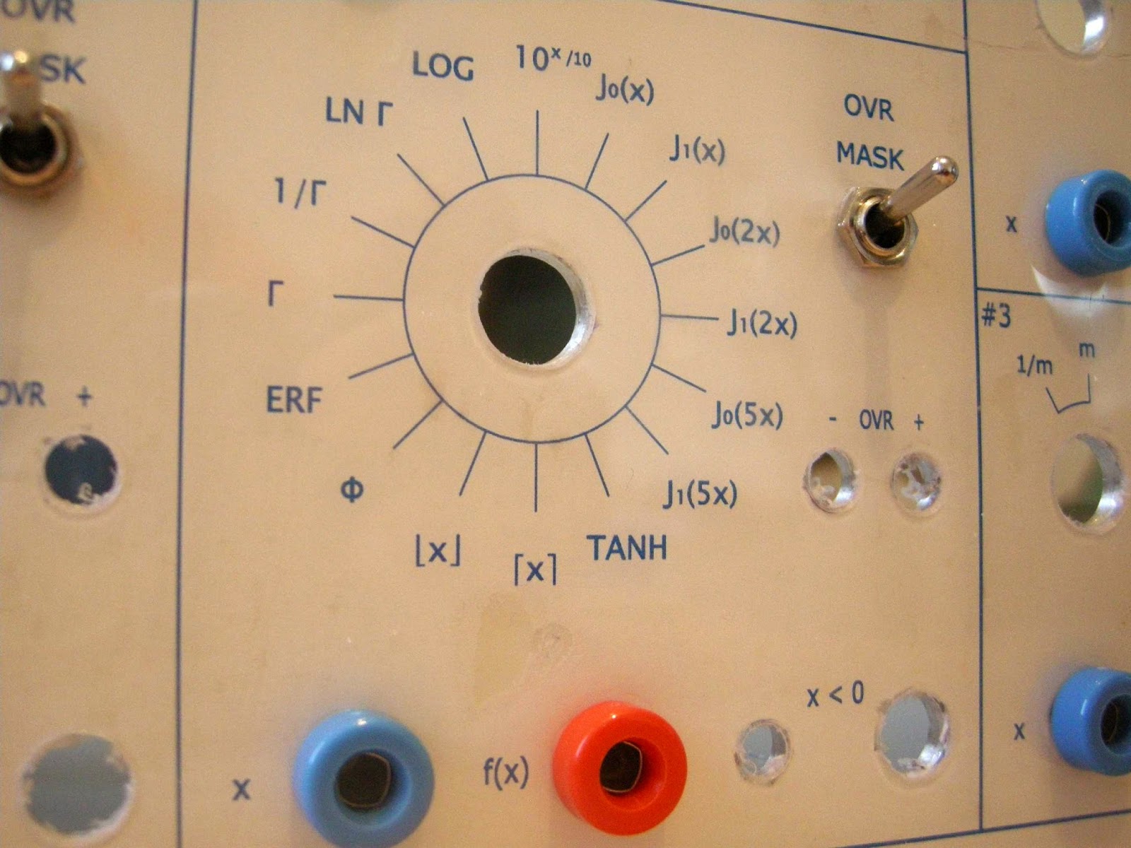
At long last, work is under way on the final rack (number four) - special functions ( I use the term somewhat loosely - trigonometric functions are here also). A slight hiatus whilst I await delivery of some orange banana jacks (from USA - we have nothing like that over here!). Front panel drilled and being populated...so far the thing looks like this:


Zero Limiters

The final board...essentially just a couple of ideal diodes / precision rectifiers:


There's also an analog switch (DG403) too (the pins of this are just taken to jacks on the front panel - for the user to make use of as he/she sees fit).


Limiter

Here's the limiter circuit (one of two separate channels is shown):


It's based on a circuit from 1959 [1]; the glass 6AL5s being replaced by the also glass 1N4148s:


Trimmer C1 is retained and proves useful in setting the left (or right) part of the transfer characteristic flat. 


[1] 'Function Generation With Operational Amplifiers', H. Koerner and G. A. Korn, Electronics, November 6, 1959, pp. 66-70.

Wednesday, December 10, 2014

Dead Space

Mathematically:

f(x) = 0             a < x < b;
f(x) = (x - b)     x > b;
f(x) = (x + a)    x  < a .

The transfer function (from Johnson 'Analog Computer Techniques', 1956, page 115) looks like this:


 Here's my realisation of the circuit (sans vacuum tubes):
The final thing has two separate channels:


Saturday, December 6, 2014

Equality

My second (and this time successful) attempt at what I naively assumed would be a straightforward thing to implement: to test when two voltages are 'equal':


The INA128 (which has very low offset voltage) is configured to give a gain of about 500; any significant difference in X and Y input voltages gives rise to a significant voltage (positive or negative) - the TL071 op amp inverts the output of the INA128; the output of this op amp and the direct output are put through the Schottky diodes - hence regardless of the sign of the voltage difference, the base of the first transistor is driven high when X does not equal Y. The base of the second transistor goes high when X = Y, as does its emitter! 

The actual circuit has two independent X = Y channels:


In the scope display below, the horizontal axis is 20 microseconds / division; the triangle wave (i.e. X) (5 kHz) is 20 mV / division; Y = 0 volts. The X = Y output (which appears on the computer's front panel) is 0 to 10 V. In practice, the circuit detects X = Y when X is within +/- 10 mV of Y, for X and Y in the range -10 V through +10 V.


The DG403 chip (shared between channels) provides normally open and closed switching - these outputs also appear on the front panel.

Sunday, November 30, 2014

Inequality

This circuit detects X < Y - it is what in the old days was called a differential relay (a single pole double throw switch driven by the output of an operational amplifier) - in this circuit the relay of old is realised via a CMOS analog switch (DG403). In my circuit, the output of a INA128 instrumentation amplifier drives a couple of transistors to get the gain up enough so that the output switches for about a 5 mV difference in inputs. An LED on the computer's front panel will indicate X < Y; there is a 10 V output also for this condition.


Next board is X = Y (which is proving surprisingly complicated!)

Saturday, November 22, 2014

Off On a Tangent

Have finally completed the special function circuitry...in the end I moved (temporarily) to the dark side...buying a few AT28C64B EEPROMs and a MiniPro TL866 programmer.

The EEPROM is sandwiched between a AD7820 8 bit ADC and a AD7224 DAC. The ADC drives eight of the (64K) EEPROM's addresses; one is driven by the output of a sign detection op amp; the remaining four address bits are connected to a Lorlin binary-coded (16-position) rotary switch. Each switch position gives a separate function. The ADC / DAC are clocked at about 360 kHz.

The absolute value of the input voltage (scaled so that 0 - 10.2 V input voltage maps to 0 to 5.000 V at the input to the ADC), drives the ADC; the sign of the input voltage drives an address bit of the EEPROM. Hence negative and positive halves of the function's domain occupy separate parts of the memory.

Here's the circuit. The MC14495 display drivers and displays (included in anticipation of the thing not working!) were omitted in the final design.


The contents of the EEPROM was cooked up using a MATLAB program - it's easy enough to have any functions (single-valued!) I like - I've opted for the usual suspects - sine, cosine, tangent; their inverses; their hyperbolic cousins; logarithm, exponentiation...plus some slightly more esoteric things (Bessel, error, gamma...)

sine


tanh

cosh
tangent
Negative and positive overflow are determined by all zeros or all ones from the EEPROM output - using a NOR gate and NAND gate respectively; since the pin-outs of a 4068 and 4078 are the same I got away with piggy-backing the chips:


(Reminds me of when I had a TI-59 calculator - needless to say I dismantled the thing to have a look...I think I am correct in saying that at least one of the chips (TMC 0583?) was soldered (presumably by hand!) directly onto another chip...that was an amazing bit of circuitry - it even had a LM324 quad op amp in there...)